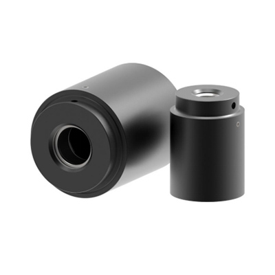
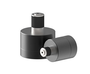
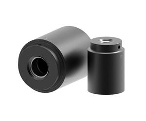
KLW series quick connector technical parameters
Working pressure: inlet B: from vacuum to a maximum of 35 bar, other pressure ranges are available on request. When applied in a pressurized environment, the KLW series quick connector must be fixed by a fixing device. For vacuum applications, no fixing device is required. For working pressures above 10 bar, urethane is recommended. For seals, the control pressure must be increased accordingly, for example using a pressure regulator that controls the pressure.
Operating pressure: inlet P: 4 to 12 bar clean compressed air, pressure regulator with control pressure, hydraulic pressure up to 42 bar.
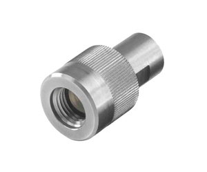
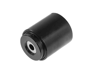
Design: The housing, piston and washer are made of aluminum alloy.
Seal: The main seal and O-ring are made of nitrile rubber (NBR).
Urethane seals are available for wear-resistant applications.
Leakage rate:
10-3 mbar × l / s (10-4Pa × m3 / s)
*This is the standard minimum leak rate, we can provide lower leakage rate devices on demand, depending on the detailed specifications (test method, test temperature and test pressure) provided by the customer and the quality of the samples provided by the customer (ie sealing surface) Surface treatment conditions, roughness and dimensions allow tolerances).
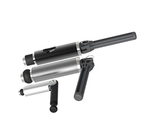
Steps for usage:
1. Fix the quick connector with the fixing clamp; insert the test piece into the quick connector, apply the control air source, seal the connection of the quick connector, and apply the test pressure.
2. When the connection is disconnected, the test pressure is released first, and then the control pressure is released. Move the quick connector away.
Specification size (mm):
Dimensions Test port B Drive port P Mounting port G D1 D2 D3 L1 L2
001* G1/8′′ M5 M3 21.3 --- 16 43.7 ---
1 G1/8′′ M5 M5 37.8 32.5 27.9 52.1 9.5
1 G1/4′′ G1/8′′ M6 56.4 46.9 41.1 69.1 9.6
2 G1/2′′ G1/8′′ M6 79 68.8 63.5 88.9 14.5
3 G1′′ G1/8′′ M6 107.4 91 82.5 113.8 29.5
4 G1 1/2′′ G1/8′′ M6 139.2 122 108 116.8 27.7
5 G2′′ G1/8′′ M10 177.3 161.8 139.7 116.8 35.3
6 G2 1/2′′ G1/8′′ M10 190 174.5 155.4 126.2 35.3
Specifications are expressed in mm
"*" represents the outer dimension 001, and the 'P' is located above the diameter of the quick connector, not on its surface.
|
Shape size
|
Seal range A
|
Lmin*(mm)
|
KLW type
|
Plugging part number
|
|
Replace the seal
|
|
(mm)
|
Part number
|
Including: plugging fast connector
|
|
Part number
|
|
|
Including: test fast connector
|
seal kit
|
Seal number
|
Sealing replacement
|
|
|
seal kit
|
|
|
|
|
1
|
0.80-1.30
|
4
|
KLW001-0050
|
KLW001-0050 P
|
1
|
KLW001-0050NBR
|
|
1
|
1.30-1.80
|
4
|
KLW001-001
|
KLW001-001 P
|
1
|
KLW001-001NBR
|
|
1
|
1.80-2.30
|
4
|
KLW001-002
|
KLW001-002 P
|
1
|
KLW001-002NBR
|
|
1
|
2.30-2.80
|
4
|
KLW001-003
|
KLW001-003 P
|
1
|
KLW001-003NBR
|
|
1
|
2.80-3.30
|
4
|
KLW001-004
|
KLW001-004 P
|
1
|
KLW001-004NBR
|
|
1
|
2.50-3.50
|
14.7
|
KLW01-01
|
KLW01-01 P
|
1
|
KLW01-01NBR
|
|
1
|
3.50-4.50
|
14.7
|
KLW01-02
|
KLW01-02 P
|
1
|
KLW01-02NBR
|
|
1
|
4.50-5.50
|
14.7
|
KLW01-03
|
KLW01-03 P
|
1
|
KLW01-03NBR
|
|
1
|
5.50-6.50
|
14.7
|
KLW01-04
|
KLW01-04 P
|
1
|
KLW01-04NBR
|
|
1
|
6.50-7.50
|
14.7
|
KLW01-05
|
KLW01-05 P
|
1
|
KLW01-05NBR
|
|
1
|
7.50-8.50
|
14.7
|
KLW01-06
|
KLW01-06 P
|
1
|
KLW01-06NBR
|
|
1
|
8.50-9.50
|
14.7
|
KLW01-07
|
KLW01-07 P
|
1
|
KLW01-07NBR
|
|
1
|
9.50-10.50
|
14.7
|
KLW01-08
|
KLW01-08 P
|
1
|
KLW01-08NBR
|
|
1
|
10.50-11.50
|
14.7
|
KLW01-09
|
KLW01-09 P
|
1
|
KLW01-09NBR
|
|
1
|
11.0-12.0
|
15.5
|
KLW1-11
|
KLW1-11 P
|
1
|
KLW1-11NBR
|
|
1
|
12.0-13.0
|
15.5
|
KLW1-12
|
KLW1-12 P
|
1
|
KLW1-12NBR
|
|
1
|
13.0-14.0
|
15.5
|
KLW1-13
|
KLW1-13 P
|
1
|
KLW1-13 NBR
|
|
1
|
14.0-15.0
|
15.5
|
KLW1-14
|
KLW1-14 P
|
1
|
KLW1-14 NBR
|
|
1
|
15.0-16.0
|
15.5
|
KLW1-15
|
KLW1-15 P
|
1
|
KLW1-15 NBR
|
|
1
|
16.0-17.0
|
15.5
|
KLW1-16
|
KLW1-16 P
|
1
|
KLW1-16 NBR
|
|
1
|
17.0-18.0
|
15.5
|
KLW1-17
|
KLW1-17 P
|
1
|
KLW1-17 NBR
|
|
1
|
18.0-19.0
|
15.5
|
KLW1-18
|
KLW1-18 P
|
1
|
KLW1-18 NBR
|
|
1
|
19.0-20.0
|
15.5
|
KLW1-19
|
KLW1-19 P
|
1
|
KLW1-19 NBR
|
|
2
|
20.0-21.5
|
26.9
|
KLW2-21
|
KLW2-21 P
|
2
|
KLW2-21 NBR
|
|
2
|
21.5-23.0
|
26.9
|
KLW2-22
|
KLW2-22 P
|
2
|
KLW2-22 NBR
|
|
2
|
23.0-24.5
|
26.9
|
KLW2-23
|
KLW2-23 P
|
2
|
KLW2-23 NBR
|
|
2
|
24.5-26.0
|
26.9
|
KLW2-24
|
KLW2-24 P
|
2
|
KLW2-24 NBR
|
|
2
|
26.0-27.5
|
26.9
|
KLW2-25
|
KLW2-25 P
|
2
|
KLW2-25 NBR
|
|
2
|
27.5-29.0
|
26.9
|
KLW2-26
|
KLW2-26 P
|
2
|
KLW2-26 NBR
|
|
2
|
30.5-32.0
|
26.9
|
KLW2-27
|
KLW2-27 P
|
2
|
KLW2-27 NBR
|
|
2
|
33.5-35.0
|
26.9
|
KLW2-28
|
KLW2-28 P
|
2
|
KLW2-28 NBR
|
|
2
|
35.5-37.0
|
26.9
|
KLW2-29
|
KLW2-29 P
|
2
|
KLW2-29 NBR
|
|
3
|
38.0-40.0
|
41.7
|
KLW3-31
|
KLW3-31 P
|
3
|
KLW3-31 NBR
|
|
3
|
40.0-42.0
|
41.7
|
KLW3-32
|
KLW3-32 P
|
3
|
KLW3-32 NBR
|
|
3
|
42.0-44.0
|
41.7
|
KLW3-33
|
KLW3-33 P
|
3
|
KLW3-33 NBR
|
|
3
|
44.0-46.0
|
41.7
|
KLW3-34
|
KLW3-34 P
|
3
|
KLW3-34 NBR
|
|
3
|
46.0-48.0
|
41.7
|
KLW3-35
|
KLW3-35 P
|
3
|
KLW3-35 NBR
|
|
3
|
48.0-50.0
|
41.7
|
KLW3-36
|
KLW3-36 P
|
3
|
KLW3-36 NBR
|
|
4
|
50.0-52.0
|
41.7
|
KLW4-41
|
KLW4-41 P
|
3
|
KLW4-41 NBR
|
|
4
|
52.0-54.0
|
41.7
|
KLW4-42
|
KLW4-42 P
|
3
|
KLW4-42 NBR
|
|
4
|
54.0-56.0
|
41.7
|
KLW4-43
|
KLW4-43 P
|
3
|
KLW4-43 NBR
|
|
4
|
56.0-58.0
|
41.7
|
KLW4-44
|
KLW4-44 P
|
3
|
KLW4-44 NBR
|
|
4
|
58.0-60.0
|
41.7
|
KLW4-45
|
KLW4-45 P
|
3
|
KLW4-45 NBR
|
|
4
|
60.0-62.0
|
41.7
|
KLW4-46
|
KLW4-46 P
|
3
|
KLW4-46 NBR
|
|
4
|
62.0-64.0
|
41.7
|
KLW4-47
|
KLW4-47 P
|
3
|
KLW4-47 NBR
|
|
4
|
64.0-66.0
|
41.7
|
KLW4-48
|
KLW4-48 P
|
3
|
KLW4-48 NBR
|
|
5
|
66.0-68.0
|
41.7
|
KLW4-49
|
KLW4-49 P
|
3
|
KLW4-49 NBR
|
|
5
|
68.0-70.0
|
41.7
|
KLW5-51
|
KLW5-51 P
|
3
|
KLW5-51 NBR
|
|
5
|
70.0-72.0
|
41.7
|
KLW5-52
|
KLW5-52 P
|
3
|
KLW5-52 NBR
|
|
5
|
72.0-74.0
|
41.7
|
KLW5-53
|
KLW5-53 P
|
3
|
KLW5-53 NBR
|
|
5
|
74.0-76.0
|
41.7
|
KLW5-54
|
KLW5-54 P
|
3
|
KLW5-54 NBR
|
|
5
|
76.0-78.0
|
41.7
|
KLW5-55
|
KLW5-55 P
|
3
|
KLW5-55 NBR
|
Special type of KLW series fast connector
If the standard type can not meet your requirements, we will provide you with exclusive solutions. Welcome to consult.